I. Pre – Installation Preparation
Interface inspection: Conduct a comprehensive check of all types of interfaces on the terminal, including power supply interfaces, antenna interfaces, communication interfaces, and network interfaces, to ensure that all interfaces are intact and functional.
Tool preparation: Gather all the necessary tools for installation, including but not limited to open – end wrenches, screwdrivers, and Ethernet cables, to ensure a smooth installation process.
Cabling planning: Based on the specific usage scenario of the in – vehicle communication terminal, plan the cabling positions for the 5G antenna, power cable, and network cable in a reasonable manner. Ensure that the cabling is neat and does not interfere with the normal operation of the vehicle.
II. Terminal Installation Steps

Location selection: Choose a suitable installation location that is concealed within the vehicle and does not interfere with communication. This ensures the stability and security of the terminal.
Chassis removal: Use an open – end wrench to remove the screws from the terminal chassis and carefully take off the chassis to proceed with the subsequent installation work.
Terminal fixation: Securely fix the terminal in the selected location using self – tapping screws. Ensure that it does not shake or fall off during vehicle operation.
Chassis reinstallation: After the terminal is fixed, reinstall the chassis and make sure all screws are tightened.
III. Wiring and Connections
Power cable connection: Correctly connect the vehicle power supply to the terminal’s power interface, paying attention to the polarity to avoid faults caused by reversed connections.
SIM card installation: Open the terminal’s card slot cover, insert the SIM card into the slot, and close the cover. Ensure that the SIM card is recognized and functional.
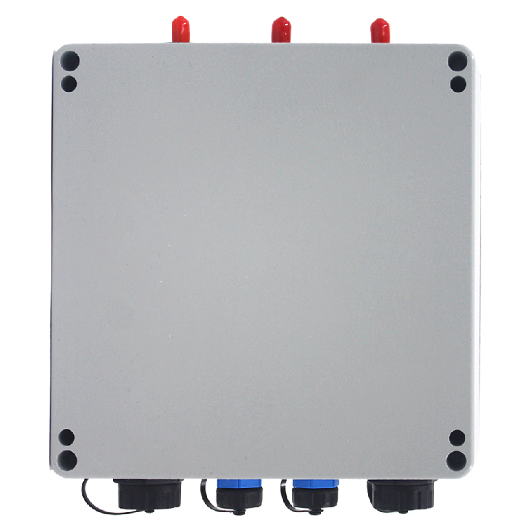
Antenna connection: Connect the 5G antenna and optional WiFi antenna to the terminal’s antenna interfaces, ensuring a secure connection and stable signal transmission.
Network cable connection: Connect the router’s LAN interface to the terminal’s WAN port using an Ethernet cable to establish a normal network connection.
Power connection and inspection: Finally, connect the power supply and check whether the terminal’s operation indicator light is on normally to confirm that the terminal is in a working state.
IV. Parameter Configuration and Settings
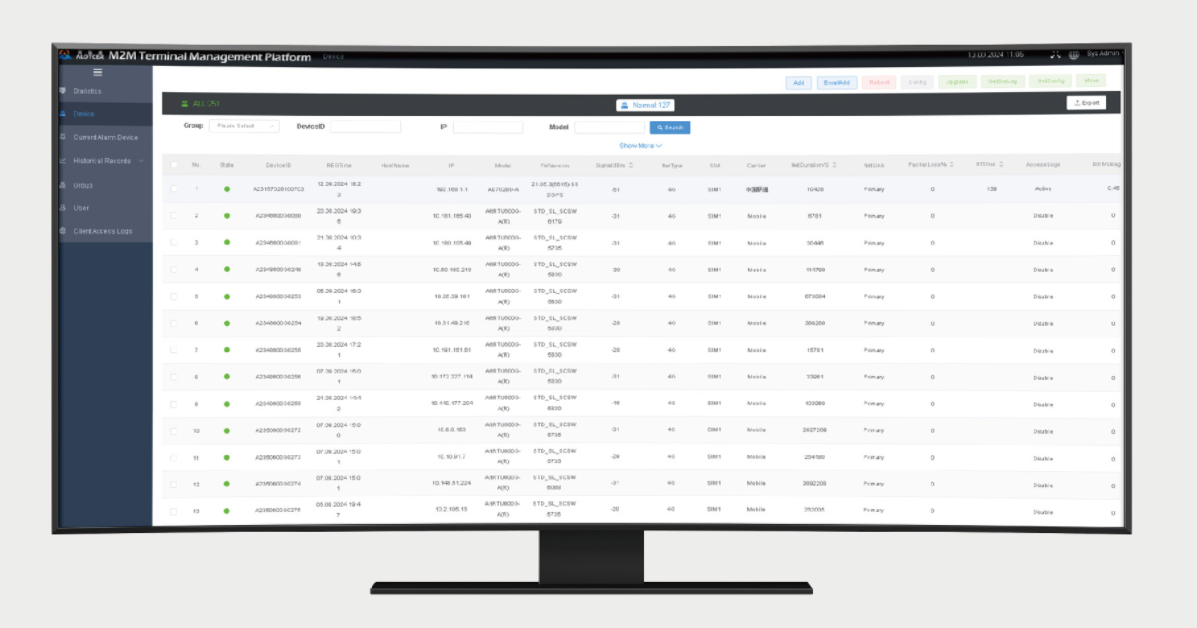
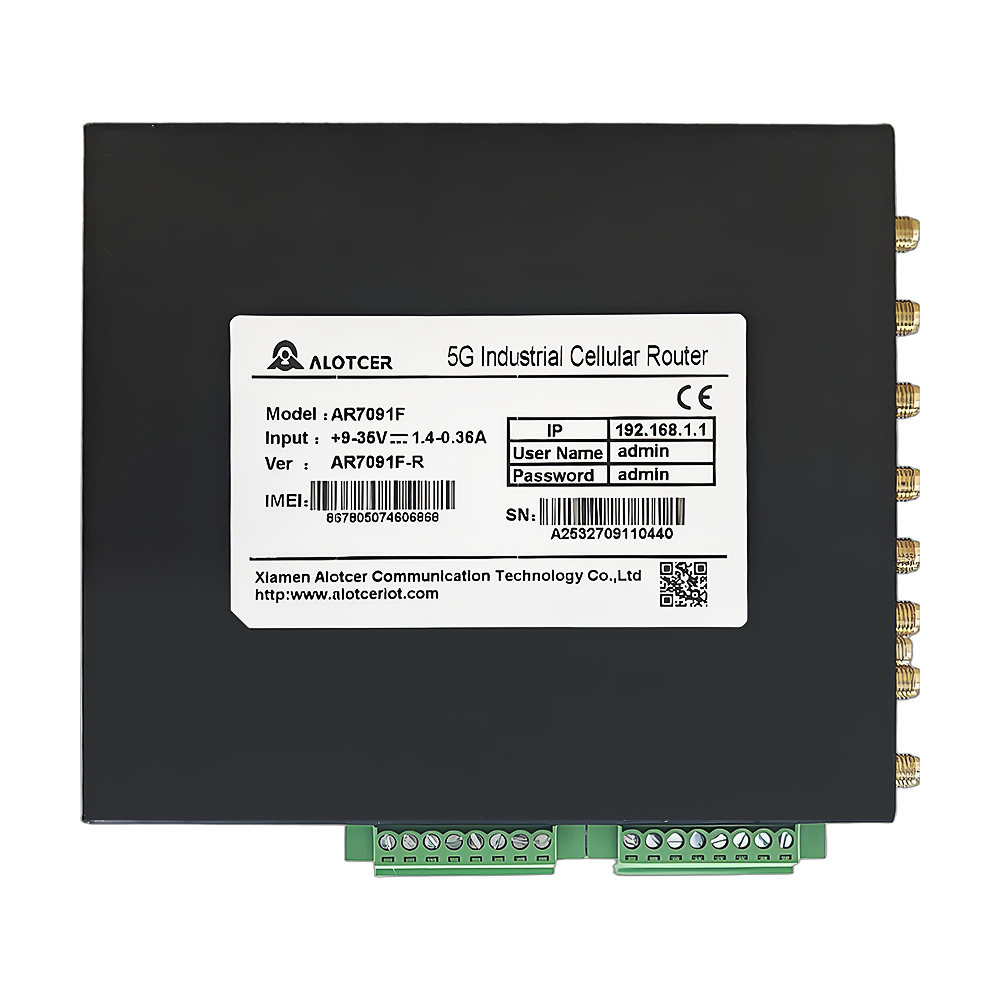
Log in to the WEB interface: Access the terminal’s WEB interface through the router’s LAN IP address and enter the network settings interface.
SIM card parameter settings: Configure key information such as the SIM card’s APN parameters and authentication method to ensure normal network access.
WiFi parameter configuration: Set parameters such as the WiFi SSID, password, and channel to meet the wireless communication needs of in – vehicle applications.
IP routing settings: Configure IP routing parameters, including DHCP service and port mapping, to ensure smooth and stable network communication.
V. Routine Maintenance and Care
Interface inspection and reinforcement: Regularly check whether the terminal’s interfaces are loose. For important interfaces, apply anti – slip tape for reinforcement.
Cleaning: Regularly clean the antenna and ventilation holes to prevent dust and dirt accumulation from affecting communication performance and heat dissipation.
Signal monitoring and adjustment: Monitor the network signal strength and adjust the antenna angle if necessary to improve signal reception quality.
Software updates: Timely update the terminal’s software version to fix known security vulnerabilities and enhance system stability.
Device reboot and cache cleaning: Periodically reboot the device and clear the cache to release system resources and optimize performance.
Through professional installation and rational configuration, in – vehicle communication terminals can operate stably in harsh vehicle environments, providing reliable and efficient communication support for various in – vehicle applications.